You’ll need to establish 2-3 inch clearances between moving components and static structures while ensuring your prop doesn’t exceed 12 feet in total height. Start by building foundations that handle both static loads and operational stresses, then reinforce wooden gears with dowels and three layers of paper mache mesh. Use adjustable angle connectors at pivot points, partially tightening bolts to create friction that holds desired angles. Layer dissimilar materials at high-stress zones and conduct rigorous testing that simulates real-world handling—the complete assembly sequence reveals techniques that professional builders rely on every production.
Key Takeaways
- Plan minimum 2-3 inch clearances between moving components and static structures, mapping complete movement range from initial to maximum extension positions.
- Design foundations to handle both static loads and operational stresses, calculating worst-case scenarios for actors and vibrating loads.
- Reinforce wooden gears with dowels and three layers of paper mache mesh, clamping assemblies for 24 hours with even pressure.
- Use adjustable angle connectors at pivot points, partially tightening bolts to allow manual adjustment while preventing unwanted rotation.
- Test assemblies rigorously through visual inspection, electrical connectivity verification, and complete motion sequences under load conditions.
Planning Movement and Clearance in Your Design
When designing props with movable parts, you must account for both the range of motion and the physical clearances required to operate safely. Start by establishing minimum clearances—typically two to three inches between moving components and static structures to prevent collisions during operation. Map out your complete movement range, from initial position through maximum extension, ensuring adequate space throughout the cycle.
Staging height requirements directly impact your clearance planning. Props can’t exceed 12 feet total height including wheels and railings, with performer safety protocols mandating guard rails or harnesses at six feet. Measure moving parts in both retracted and extended positions, factoring in structural margins for vibration and operational stress. Match your design complexity to your team’s technical abilities, then develop thorough training protocols for safe operation under various conditions.
Building Strong Foundations for Dynamic Components
Because dynamic components generate forces that can quickly compromise unstable props, your foundation must handle both static loads and operational stresses from the first build. You’ll need flexible frame design that accommodates motors, compressors, and moving mechanisms while maintaining structural integrity.
Dynamic props demand foundations engineered for both static weight and operational forces from initial construction through final performance.
Calculate worst-case scenarios—if actors will stand, sit, or throw your prop, extrapolate these forces when sizing your foundation.
Weight distribution planning becomes critical for vibrating loads. Design block foundations with center of gravity nodes positioned to counteract operational forces. For complex assemblies, establish rigid frames that provide support without restricting movement.
Your foundation dimensions directly correlate to component forces; for example, substantial dynamic systems may require bases measuring 27.5 feet by 15.75 feet. Select materials like wood or foam-core based on required strength and durability under continuous operation.
Creating Rotating Mechanisms With Gears and Dowels
When building gears for rotating props, you’ll need to reinforce them with wooden dowels to handle the mechanical stress of continuous operation. Insert dowels through the center of your gear blanks before layering paper mache mesh over the structure—this creates a rigid core that prevents warping and breakage during use.
Apply three layers of paper mache with mesh reinforcement, ensuring each layer dries completely before adding the next to maximize strength without adding unnecessary weight.
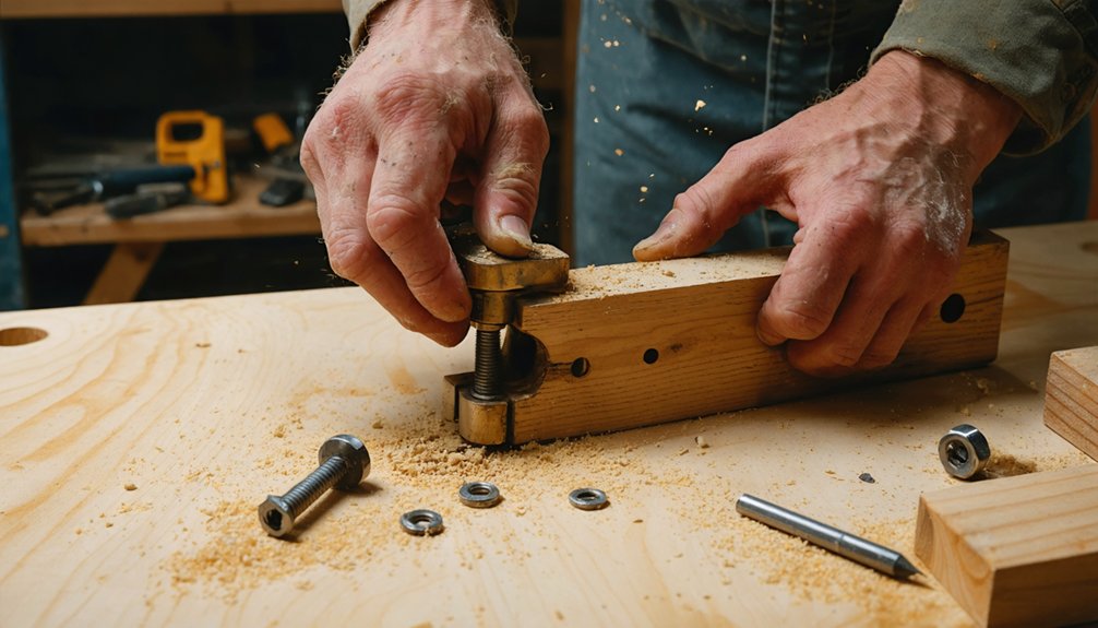
Reinforcing Gears With Dowels
Though wooden gears look simple, they require substantial reinforcement to withstand the mechanical stress of continuous rotation. Proper dowel retention methods guarantee your gear teeth remain secure during operation. You’ll need to focus on dowel joint strength through these proven techniques:
- Apply wood glue inside drilled holes before inserting dowels, ensuring complete coverage without voids
- Clamp assemblies for 24 hours with even pressure across all joints to prevent gaps
- Avoid over-tightening clamps which squeezes out essential glue needed for bond strength
- Install threaded inserts using thickened epoxy within dowel holes for additional mechanical reinforcement
Hardwood dowels like oak provide superior durability when sized at ⅓ of your board thickness. Match drill bit diameter precisely to dowel size for perfect fit and maximum holding power.
Layering Paper Mache Mesh
Paper mache mesh creates lightweight yet rigid shells around rotating mechanisms while maintaining clearance for moving parts. You’ll apply 3-4 initial layers of newspaper strips in random directions over your gear assembly, ensuring you don’t bond moving components together. Tear strips into 1/2-inch widths and dip them in your water-based glue mixture diluted to milk-like consistency.
For paper mache sculpting around axles, notch your strips to wrap snugly without bunching. Press your fingernail into edges where gears meet housing to maintain crisp definition. Alternate strip directions across layers for maximum strength. Allow each application to dry completely before adding 2-3 additional layers.
This layering paper strips technique builds durable housings that protect mechanisms while keeping rotational parts free-moving and functional.
Articulated Joints Using Adjustable Angle Connectors
When you’re building articulated props like posable wings or mechanical limbs, adjustable angle connectors transform rigid EMT conduit frames into movable assemblies. Position these connectors at strategic pivot points where you need controlled rotation—partially tighten the bolt and nut to create friction that holds your desired angle while still allowing manual adjustment.
This approach lets you achieve dynamic positioning between 0° and 180°, giving you the angular control that fixed 45° or T-connectors can’t provide for non-standard geometries.
Connector Placement for Movement
Because adjustable angle connectors contain built-in pivot mechanisms, you can transform them from rigid structural joints into functional hinges by simply leaving the top bolt partially tightened. This creates articulation points where you need controlled movement in your prop designs.
Strategic placement requires considering both connector strength considerations and mounting orientation strategies:
- Position at vertical pipe tops for angled bracing that swings outward or inward
- Mount in-clamp on frame horizontals to create pivoting attachment points for moving components
- Install at stress points where galvanized models supporting 500kg static loads guarantee durability
- Orient puzzle clamps on through-pipes while end clamps terminate at movement endpoints
Your connector placement directly affects range of motion—the 0° to 180° adjustability means you’ll achieve dynamic angles impossible with fixed T-connectors or standard 45° fittings.
Creating Dynamic Wing Assemblies
Strategic connector placement sets the foundation for movement, but dynamic wing assemblies demand a complete articulation system that transforms static framework into functional mechanics. You’ll need linear actuators positioned along your wing’s structural frame stability points, enabling synchronized extension and retraction cycles.
Dual short-throw designs offer reliable articulation while maintaining lightweight construction—critical for manageable prop weight.
Integrate actuator power systems directly into your backpack frame, clamping small battery units to structural members for efficient weight distribution. Your aluminum u-channel construction provides the necessary rigidity; doubled structural members, inspired by umbrella engineering, deliver superior stability under articulation loads.
Secure joints using washers, bolts, and nylon spacers, creating adjustable connections between wing segments. This complete mechanical integration enables controlled, repeatable movement throughout your dynamic assembly.
Achieving Controlled Angular Motion
Adjustable angle connectors transform rigid pipe frameworks into adaptable articulation systems through their multi-position hinge design. These steel hinges lock securely at any angle up to 90 degrees in both directions, enabling you to position braces and supports where standard fixed connectors can’t reach. You’ll achieve controlled motion by partially tightening the bolts—tight enough to prevent unwanted rotation but loose enough for deliberate repositioning.
Assembly sequence for ideal joint function:
- Insert the nut into the bottom pocket and hand-thread the bolt before tightening with your 5mm hex wrench
- Position your through pipe at the desired angle
- Fully tighten the upper bolt to lock the angle
- Retighten the lower bolt after securing materials
The nut pocket design allows single-tool assembly from either side, streamlining your workflow when building complex articulated props.
Reinforcement Strategies for Parts Under Stress
When you build props with moving parts, the points where components connect and pivot will face repeated stress that can lead to cracking, warping, or complete failure. You’ll need to strategically strengthen these vulnerable areas before problems emerge.
Focus on stress distribution by enlarging contact surfaces at joints—wider bearing points prevent concentrated force from overwhelming single locations. Consider material flexibility when selecting reinforcement components; combining rigid frameworks with slightly elastic buffers absorbs impact energy effectively.
Layer dissimilar materials at high-stress zones. Metal washers paired with leather or rubber gaskets create interfaces that accommodate movement while protecting softer substrates. Apply structural adhesives beyond mechanical fasteners for redundant security. Reinforce thin sections with internal armatures, and add gussets or corner braces where perpendicular elements meet, transforming weak angles into load-bearing triangles.
Testing and Troubleshooting Moving Assemblies
Before your prop leaves the workshop, put it through rigorous testing that simulates real-world handling and operation. You’ll need thorough electrical testing procedures to verify your moving assemblies function reliably under stress.
Start with board bring up testing to initialize and verify overall operation, then validate against your design specifications:
- Visual inspection – Check mechanical joints, solder connections, and component placement for obvious defects
- Connectivity testing – Verify all electrical paths between motors, sensors, and controllers for shorts or opens
- Functional validation – Run complete motion sequences under load conditions to confirm performance
- Stress testing – Cycle assemblies repeatedly to reveal early failures before deployment
Document every failure mode you discover—this debugging data becomes invaluable for refining future designs and troubleshooting field issues.
Frequently Asked Questions
What Lubricants Work Best for Maintaining Smooth Movement in Prop Mechanisms?
You’ll find silicone-based lubricants and Teflon-based lubricants work exceptionally well for prop mechanisms. They create durable, non-stick coatings that resist dust attraction while maintaining smooth operation. Apply them to fast-moving parts where traditional greases would collect debris and compromise performance.
How Do You Weatherproof Moving Parts for Outdoor Events or Performances?
You’ll weatherproof moving parts by sealing electrical connections with silicone, elevating mechanisms on platforms, and ensuring proper ventilation for exposed mechanisms. Focus on material considerations for outdoor durability—use waterproof coatings, weatherproof enclosures, and secure everything with stakes and weighted bases.
Can You Add Motors to Hand-Cranked Mechanisms for Automated Movement?
Though it seems complex, you’ll find conversion straightforward—replace hand cranks with battery powered actuation using DC motors and gear ratios. Servo driven mechanisms offer precise control for automated movement, transforming manual props into remotely operated systems with minimal modifications.
What’s the Best Way to Hide Mechanical Components for Cleaner Aesthetics?
Use discreet mounting techniques like recessed cavities and internal foam channels to conceal motors and wiring. Embrace minimalist component design by selecting compact electronics, routing cables along hidden seams, and integrating mechanics within hollow resin casts for seamless exteriors.
How Do You Balance Weight Distribution When Adding Heavy Moving Parts?
Think of your prop as a seesaw—you’ll need precise center of gravity considerations when mounting heavy actuators. Apply weight dispersal techniques by adding counterweights to the lighter blade’s hub using lead shot, adjusting incrementally until it hangs level during static checks.